# Arduino IDE con IoT: ESP32 + Sensores externos + IoT
##### **OBJETIVO**
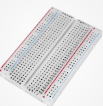
Ahora vamos a utilizar el ESP32 SIN EL ARDUINO ALVIK podemos sacar la placa microcontroladora y ponerlo en una placa *protoboard* y experimentar con sensores y actuadores estándares en el mercado :
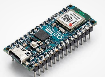 + 
Para ver varias posibilidades, vamos a ver estos sensores y actuadores (recomendamos ver estas páginas [actuadores ](https://libros.catedu.es/books/programa-arduino-mediante-codigo/page/actuadores-y-otras-salidas-GLB)y [sensores](https://libros.catedu.es/books/programa-arduino-mediante-codigo/page/sensores))
- Un led de salida simple, para practicar salida digital en mi caso voy a elegir este gracioso [semáforo](https://www.tiendatec.es/maker-zone/modulos/647-modulo-semaforo-led-tres-colores-para-arduino-8406471540007.html)
- Un [sensor LDR ](https://solectroshop.com/es/sensores-de-luz-y-de-color/1299-sensor-digital-de-intensidad-de-luz-con-foto-resistencia-ldr-con-controlador-lm393.html)pero para practicar los dos tipos de señal,
- con salida analógica
- con salida digital.
- Un [sensor CO2 CCS811 ](https://wiki.keyestudio.com/KS0457_keyestudio_CCS811_Carbon_Dioxide_Air_Quality_Sensor)con protocolo I2C
+[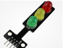](https://libros.catedu.es/uploads/images/gallery/2024-07/2024-07-15-13-11-03-semaforo-arduino-at-duckduckgo.png)+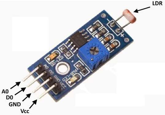+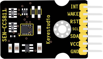
##### **ESQUEMA DE CONEXIONES**
- **SEMAFORO**
- LED ROJO al D1 del ESP32
- GND a GND
- **MODULO SENSOR LDR**
- SEÑAL DIGITAL al D0 del ESP32
- SEÑAL ANALÓGICA al A0 del ESP32
- VCC a 3V3
- GND A GND
- **MODULO SENSOR CO2**
- SCL al pin A5 del ESP32
- SDA al pin A4 del ESP32
- PIN WAKE a GND
- VCC a 3V3
- GND A GND[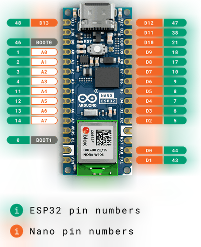](https://libros.catedu.es/uploads/images/gallery/2024-07/2024-07-07-20-14-06-alvik-user-manual-arduino-documentation.png)[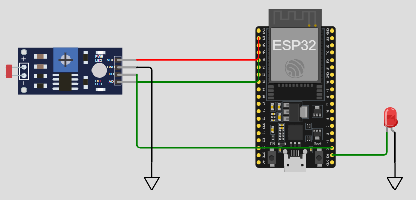](https://libros.catedu.es/uploads/images/gallery/2024-07/2024-07-15-14-47-48-new-esp32-project-wokwi-simulator.png)[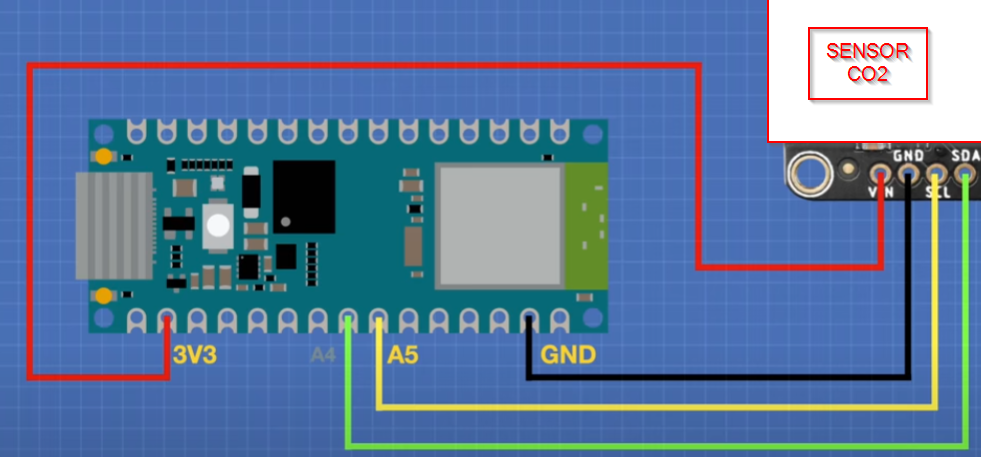](https://libros.catedu.es/uploads/images/gallery/2024-07/2024-07-15-14-08-38-1-exploring-the-arduino-nano-esp32-micropython-iot-cloud-youtube.png)
##### **DEVICES**
Nos vamos a Arduino Cloud, y en **DEVICES** añadimos el ESP32 y obtenemos el TOKEN o palabra secreta (si has hecho la práctica anterior, no es necesario pues ya tenemos el TOKEN o palabra secreta) como es similar al caso anterior, no lo desarrollamos. (Nos pedirá también el SSID y la contraseña de la red wifi)
##### **VARIABLES**
Añadimos las siguientes **variables :**
- **CO2 tipo int y Read**
- **luz tipo int y Read**
- **luzdigital tipo bool y Read**
- **rojo tipo bool y Read&Write**
##### **EL SCKETCH -LIBRERIA CCS811**
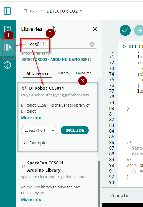
Primero añadiríamos la librería de keystudio [https://fs.keyestudio.com/KS0457](https://fs.keyestudio.com/KS0457) pero no lo permite Arduino Cloud, viendo las instrucciones, vemos que son las mismas que en los ejemplos de esta librería la de DF que es la que instalamos :
[](https://libros.catedu.es/uploads/images/gallery/2024-07/2024-07-15-13-41-58-detector-co2-thing-arduino-cloud.png)
esto provoca la incorporación de la línea 1 **\#include <DFRobot\_CCS811.h>**
##### **EL SCKETCH -EL CÓDIGO**
- Tenemos las variables definidas en las líneas 10-13 :
- **int cO2;**
- ** int luz;**
- ** bool luzdigital;**
- ** bool rojo;**
- Definimos una variable de tipo el sensor CCS811 en la línea 23 **DFRobot\_CCS811 CCS811;**
- En Setup en las líneas 48-21 arrancamos ese sensor:
- **while(CCS811.begin() != 0){**
**Serial.println("failed to init chip, please check if the chip connection is fine");**
**delay(1000);**
**}**
- Definimos los pines digitales 0 y 1 como entrada y salida respectivamente:
- **pinMode(1,OUTPUT);
pinMode(0,INPUT);**
- En las líneas 60-70 que lea el CCS811 y la parte de CO2 que lo meta en la variable CO2 (línea 63)
- **if(CCS811.checkDataReady() == true){**
**Serial.print("CO2: ");**
**Serial.print(CCS811.getCO2PPM());**
**cO2=CCS811.getCO2PPM();**
**Serial.print("ppm, TVOC: ");**
**Serial.print(CCS811.getTVOCPPB());**
**Serial.println("ppb");**
**} else {**
**Serial.println("Data is not ready!");**
**}**
- En las línea 71 que luz sea la lectura del pin A0 **luz = analogRead(A0);**
- En las líneas 72-76 que según rojo se encienda o no el led
- **if (rojo){**
**digitalWrite(1,HIGH);**
**}else{**
**digitalWrite(1,LOW);**
**}**
- En la línea 77 que luzdigital sea la lectura de la salida digital del sensor LDR
- **luzdigital=digitalRead(0);**
```c++
#include
/*
Sketch generated by the Arduino IoT Cloud Thing "Untitled"
https://create.arduino.cc/cloud/things/17c10209-3874-430a-877c-c082ff7dd38d
Arduino IoT Cloud Variables description
The following variables are automatically generated and updated when changes are made to the Thing
int cO2;
int luz;
bool luzdigital;
bool rojo;
Variables which are marked as READ/WRITE in the Cloud Thing will also have functions
which are called when their values are changed from the Dashboard.
These functions are generated with the Thing and added at the end of this sketch.
*/
#include "thingProperties.h"
//DFRobot_CCS811 CCS811(&Wire, /*IIC_ADDRESS=*/0x5A);
DFRobot_CCS811 CCS811;
void setup() {
// Initialize serial and wait for port to open:
Serial.begin(9600);
// This delay gives the chance to wait for a Serial Monitor without blocking if none is found
delay(1500);
// Defined in thingProperties.h
initProperties();
// Connect to Arduino IoT Cloud
ArduinoCloud.begin(ArduinoIoTPreferredConnection);
/*
The following function allows you to obtain more information
related to the state of network and IoT Cloud connection and errors
the higher number the more granular information you’ll get.
The default is 0 (only errors).
Maximum is 4
*/
setDebugMessageLevel(2);
ArduinoCloud.printDebugInfo();
while(CCS811.begin() != 0){
Serial.println("failed to init chip, please check if the chip connection is fine");
delay(1000);
}
pinMode(1,OUTPUT);
pinMode(0,INPUT);
}
void loop() {
ArduinoCloud.update();
// Your code here
if(CCS811.checkDataReady() == true){
Serial.print("CO2: ");
Serial.print(CCS811.getCO2PPM());
cO2=CCS811.getCO2PPM();
Serial.print("ppm, TVOC: ");
Serial.print(CCS811.getTVOCPPB());
Serial.println("ppb");
} else {
Serial.println("Data is not ready!");
}
luz = analogRead(A0);
if (rojo){
digitalWrite(1,HIGH);
}else{
digitalWrite(1,LOW);
}
luzdigital=digitalRead(0);
}
/*
Since Rojo is READ_WRITE variable, onRojoChange() is
executed every time a new value is received from IoT Cloud.
*/
void onRojoChange() {
// Add your code here to act upon Rojo change
}
```
##### **DASHBOARD**
- Un gauge ligado a **CO2** desde 0 a 2000
- Un gauge ligado a **Luz** de 0 a 2.200
- Un Switch ligado a **rojo**
- Un led de oscuridad ligado a **luzdigital**[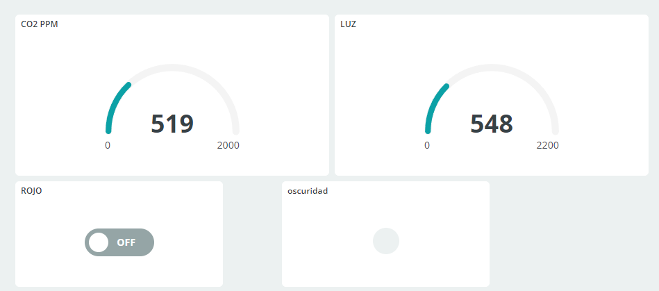](https://libros.catedu.es/uploads/images/gallery/2024-07/2024-07-15-14-16-36-co2-dashboard-arduino-cloud.png)
**Alternativa** : en vez de luz tendría que llamarse "oscuridad" que sea luz pero que vaya al revés
##### **RESULTADO**
**ALTERNATIVA:** Que el semáforo visualice los niveles peligrosos de CO2, por ejemplo el umbral del amarillo 600-1.000